|
The strips or tiles representing sections of a whole image need
to be connected. Unless you have a huge table, it would be best to arrange your sections on
the floor in their correct order.
If you selected the Glue Marks option, the scanner software will have
made your job easier by printing the following guide-markings on the panels:
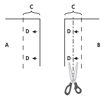
- The Cut line: a line will be printed on the left side of
panels that are to be joined with their left neighbor — that is, every panel
but the first (leftmost) panel in a row.
Use a sharp knife, scissors or other cutting device to cut on the
right edge of the line (to remove the line itself). The cutting line will be placed in the
middle of the overlap area so slight irregular cuts can be tolerated since cutout image data
will be picked up in the overlap area of the neighboring panel.
- Glue mark arrows: after cutting the edges at the cut line,
bring your panels together by overlapping with rightmost panel on top of the panel on its
left.
The second panel in a row overlaps the first panel, the third overlaps
the second and so on. Use the glue mark arrows to fit and glue the panels together with
perfect seams (see the illustration below).
You assemble the panels by bringing the arrows printed on the
overlapping panel down on top of the arrows printed on the underlying panel.
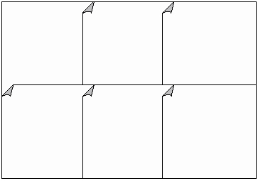
If the Tiling option is selected, cut lines and glue marks (D) will be
printed, both for horizontal connection (as illustrated above) and for vertical
connection.
Bring your panels together by overlapping the edges with each
rightmost panel (B) on top of the panel on its left (A). The second panel in a row overlaps
the first panel; the third overlaps the second and so on as illustrated below. Vertical
connection (tiling only) is performed with the first row at the lowest level and then each
following row overlaps the bottom edges of the tiles in the row before it.
|
 tell me about...