|
|
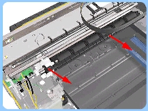
feed roller assembly |
|
| |
|
|
 |
|
Switch off the product and remove the power
cable. |
|
| |
|
|
| |
|
1. Remove the front
cover |
| |
|
|
| |
|
2. Remove the center
cover |
| |
|
|
| |
|
3. Remove the right
end cover |
| |
|
|
| |
|
4. Remove the left
end cover |
| |
|
|
| |
|
|
5. Remove the electronics
module |
|
| |
|
|
| |
|
6. Remove the starwheel
assembly |
| |
|
|
| |
|
7. Remove the output
separator |
| |
|
|
| |
|
8. Remove the output
mechanism assembly |
| |
|
|
| |
|
9. Remove the paper-axis
motor drive assembly |
| |
|
|
 |
|
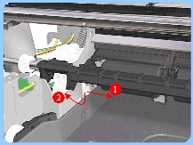
10. Release the locking mechanism from the
left hand side of the Printer.
|
| |
|
|
 |
|
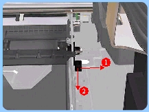
11. Release the locking mechanism
from the right hand side of the Printer.
|
| |
|
|
 |
|
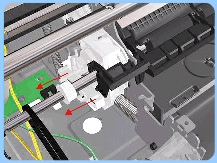
12. Release the Pin Caber and remove
from the Printer.
|
| |
|
|
 |
|
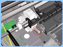
13. Release the Spring.
|
| |
|
|
 |
|
14. Raise the locks so that they are
aligned with the cutouts and lift out the
Pivot Assembly from the Printer. |
| |
|
|
| After removing or replacing the Feed Roller Assembly,
make sure that you perform the PRS Adjustment procedure and the Accuracy
Calibration. |
| |
|
|