select printer
|
70/100/100plus/110plus
|
disassembly
|
disassembly instructions
hp designjet 70/100/100plus/110plus printers
select printer
1000/1000 plus series
500/800 series
5000/5500 series
multi-roll feeder
10ps/20ps/30/30n/50ps
scanner series
70/100/100plus/110plus
90/120/130 series
4000 series printers
4500 series printers
9000s series printers
10000s series printers
Z2100/Z3100 series
8000s series printers
»
disassembly instructions
»
dissasembly instructions
»
dissasembly videos
»
top cover
»
center cover
»
right end cover
»
left end cover
»
ink supply station cover
»
ink supply station
»
electronics module
»
power supply unit
»
service station
»
front panel
»
encoder strip
»
carriage motor
»
cleanout assembly
»
ink supply tubes
»
carriage assembly
»
carriage belt
»
starwheel assembly
»
print platen assembly
»
ramp motor assembly
»
spittoon
»
pivot assembly
»
feed roller assembly
»
pick assembly
»
inner paper guide
»
OOPS sensor
»
send feedback or
comments
pick assembly
Switch off the product and remove the power cable.
1.
Remove the
Cleanout Assembly
2.
Remove the
Center Cover
3.
Remove the
Right End Cover
4.
Remove the
Left End Cover
5.
Remove the
Electronics Module
6.
Remove the
Power Supply Unit
7.
Remove the
Service Station
8.
Remove the
Encoder Strip
9.
Remove the
Carriage Assembly
10.
Remove the
Ink Supply tubes
11.
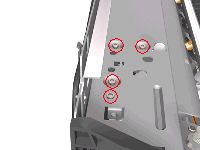
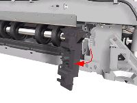
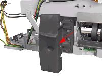
Remove 4 screws that secure the Hanger Assembly on the left hand side of the Printer.
12.
Remove 1 screw that secures the Hanger Assembly on the left hand side of the Printer.
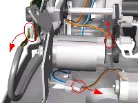
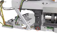
13.
Disconnect the Paper-Axis, Encoder and Ramp Motor cables.
14.
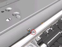
Remove 1 screw from the Rear Left Trim Bracket.
15.
Remove the Rear Left Trim Bracket from the Printer.
16.
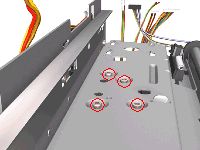
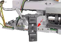
Remove 4 screws that secure the Hanger Assembly on the right hand side of the Printer.
17.
Remove 2 screws that secure the Hanger Assembly on the right hand side of the Printer.
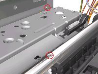
18.
Remove 1 T-10 screw from the Rear Right Trim.
19.
Remove the Rear Right Trim from the Printer.
20.
Remove 1 screw from the Rear Right Trim Bracket.
21.
Remove the Rear Right Trim Bracket from the Printer.
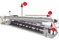
22.
Remove the Hanger Assembly from the Printer.
If there any cables still attached between the Hanger Assembly and the Printer then disconnect them before removing the Hanger Assembly.
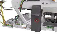
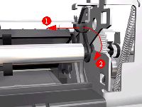
23.
Release the locking mechanism that secures the Pick Assembly on the right hand side of the printer (looking from the rear).
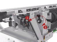
24.
Release the locking mechanism that secures the Pick Assembly on the left hand side of the printer (looking from the rear).
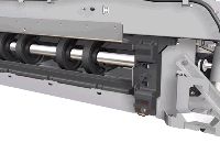
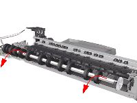
25.
Raise the locks so that they are aligned with the cutouts and lift out the Pick Assembly from the Printer.
privacy statement
using this site means you accept its terms
© 1994-2006 Hewlett-Packard Company