| |
|
||||||||||||||||||||||||||||||
|
3. Electronics Module TestThe purpose of this test is to diagnose a failure in the operation of the:
This test does not test the EIO Card or the Hard Disk Drive.
Perform the Electronics Module test as follows:
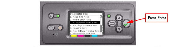
1. In the Service Tests submenu, scroll to "3. Electronics Module Test" and press Enter.
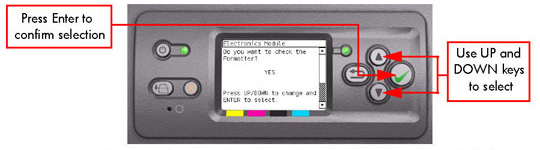
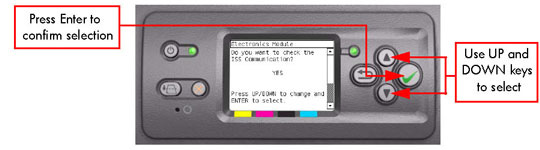
2. A message will appear on the Front Panel asking whether you would like to check the Formatter. Select Yes or No by using the Up and Down keys and press Enter to confirm your selection. If you select No, the printer skips this test and goes to the next one:
3. If you select Yes, the printer will get the CPU information and display the information on the Front Panel. Press any key to continue the test:

4. The printer will now get the Main Board (MB) information and display the information on the Front Panel. Press any key to continue the test:

5. The printer will now get the CPU Fan Speed and display the information on the Front Panel. Press any key to continue the test:

If the CPU Fan Speed is less than 2500, the Front Panel will display System Error Code 05.1:10.
6. The printer will now calculate the amount of memory installed and display the information on the Front Panel. Press any key to continue the test:

A minimum of 256 megabytes of memory must be installed in the Printer. If not, the Front Panel will display System Error Code 05.3:10.
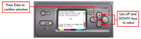
7. A message will appear on the Front Panel asking whether you would like to check the Printer Configuration. Select Yes or No by using the Up and Down keys and press Enter to confirm your selection. If you select No, the printer skips this test and goes to the next one:
8. If you select Yes, the Printer will start the CDS and the following information will be displayed on the Front Panel:
If there is a failure at this point, the Front Panel will display System Error Code 79:03.
9. The printer will then check the Serial Number and Part Number and display the information on the Front Panel. Press any key to continue the test:

If the Serial Number or the Part Number cannot be read, the Front Panel will display System Error Code 74:00.
If the Serial Number does not have assigned a correct 10 character format or the Part number does not have assigned a correct 6 character format, a fail message will appear on the Front Panel. In this case, re-enter in to the Service Tests submenu and use the diagnostic "13. Error 71:19 Recovery" to set the correct Serial Number (refer to 13. Error 71:19 Recovery).
10. The Printer will now check the unit configuration (whether it is Standard or Productivity) and the Part Number and display the information on the Front Panel. Press any key to continue the test:

If the unit configuration is incorrect according to the part number, the Front Panel will display a fail message. In this case, re-enter in to the Service Tests submenu and use the diagnostic "12. Set Unit Configuration" to set the correct configuration (refer to 12. Set Unit Configuration).
11. A message will appear on the Front Panel asking whether you would like to check the Gamut. Select Yes or No by using the Up and Down keys and press Enter to confirm your selection. If you select No, the printer skips this test and goes to the next one:

12. If you select Yes, the Printer will check the Gamut PCI PCA and the following messages will be displayed on the Front Panel:
If there is a failure at this point, the Front Panel will display System Error Code 01.0:10.
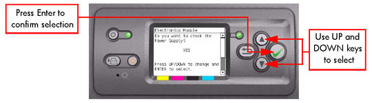
13. A message will appear on the Front Panel asking whether you would like to check the Power Supply. Select Yes or No by using the Up and Down keys and press Enter to confirm your selection. If you select No, the printer skips this test and goes to the next one:
14. If you select Yes, the Printer will check the Power Supply Unit and the following messages will be displayed on the Front Panel:
If there is a failure at this point, the Front Panel will display System Error Code 01.0:10.
If there is a failure at this point, the Front Panel will display System Error Code 03:10.
If there is a failure at this point, the Front Panel will display System Error Code 01.0:10.
If there is a failure at this point, the Front Panel will display System Error Code 03:10.
If there is a failure at this point, the Front Panel will display System Error Code 79:03.
15. A message will appear on the Front Panel asking whether you would like to check the PrintMech. Select Yes or No by using the Up and Down keys and press Enter to confirm your selection. If you select No, the printer skips this test and goes to the next one:
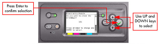
16. If you select Yes, the Printer will check the PrintMech and the following messages will be displayed on the Front Panel:
If there is a failure at this point, the Front Panel will display System Error Code 01.0:10.
The value for the PCA revision must be more than 0.625V, if not the Front Panel will display System Error Code 01.1:10.
If there is a failure at this point, the Front Panel will display System Error Code 01.0:10.
If there is a failure at this point, the Front Panel will display either System Error Code 01.0:10 or System Error Code 01.1:10.
If there is a failure at this point, the Front Panel will display System Error Code 79:03.
If the Part Number cannot be read, the Front Panel will display System
Error Code 74:00.
If the current Part Number is not in the correct 6 character format, the Front Panel will display a fail message. In this case, re-enter in to the Service Tests submenu and use the diagnostic "13. Error 71:19 Recovery" to set the correct Serial Number (refer to 13. Error 71:19 Recovery).
If the unit configuration is incorrect according to the part number, the Front Panel will display a fail message. In this case, re-enter in to the Service Tests submenu and use the diagnostic "12. Set Unit Configuration" to set the correct configuration (refer to 12. Set Unit Configuration).
17. A message will appear on the Front Panel asking whether you would like to check the Interconnect. Select Yes or No by using the Up and Down keys and press Enter to confirm your selection. If you select No, the printer skips this test and goes to the next one:
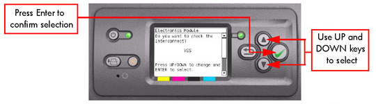
18. If you select Yes, the Printer will check the Interconnect PCA and the following messages will be displayed on the Front Panel:
If there is a failure at this point, the Front Panel will display System Error Code 79:03.
If the current Part Number is not in the correct 6 character format, the Front Panel will display a fail message. In this case, re-enter in to the Service Tests submenu and use the diagnostic "13. Error 71:19 Recovery" to set the correct Serial Number (refer to 13. Error 71:19 Recovery).
If the unit configuration is incorrect according to the part number, the Front Panel will display a fail message. In this case, re-enter in to the Service Tests submenu and use the diagnostic "12. Set Unit Configuration" to set the correct configuration (refer to 12. Set Unit Configuration).
If there is a failure at this point, the Front Panel will display System Error Code 01.0:10.
At this stage, the Printer reads and checks the default GPIO values in the Interconnect PCA when all the cables are connected and all the sensors give the default value or the current state. The results will be displayed on the Front Panel and you can press any key to scroll through the information.
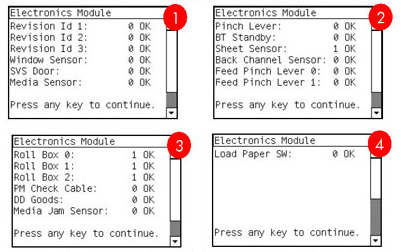
If any of the channels cannot be read, the Front Panel will display System Error Code 01.0:10.
If any of the read values do not match the expected default, the Front Panel will display System Error Code 07:10.
19. A message will appear on the Front Panel asking whether you would like to check the Carriage Communication. Select Yes or No by using the Up and Down keys and press Enter to confirm your selection. If you select No, the printer skips this test and goes to the next one:
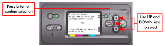
20. If you select Yes, the following message will appear on the Front Panel:

21. Open the Window and check that the Carriage power light is ON (a green light on the carriage PCA). Select Yes or No by using the Up and Down keys and press Enter to confirm your selection.
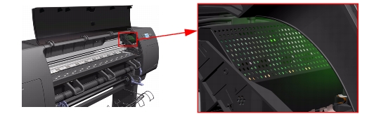
If you select No at this point, the Front Panel will display System Error Code 07:10. Check also System Error Code 11:10 or System Error Code 02.1:10.
If you select Yes, then the Front Panel will display:
If there is a failure at this point, the Front Panel will display System Error Code 02.1:10. Check also System Error Code 11:10 or System Error Code 01.0:10.
If there is a failure at this point, the Front Panel will display System Error Code 02.1:10. Check also System Error Code 11:10.
22. A message will appear on the Front Panel asking whether you would like to check the ISS Communication. Select Yes or No by using the Up and Down keys and press Enter to confirm your selection. If you select No, the printer skips this test and goes to the next one:
23. If you select Yes, the Printer will check the ISS Communication and the following information will be displayed on the Front Panel:
If there is a failure at this point, the Front Panel will display System Error Code 01.0:10.
The value for the ISS PCA revision must be more than 0.625V, if not the Front Panel will display System Error Code 01.2:10. Check also System Error Code 01.0:10.
If there is a problem in reading the values, the Front Panel will display System Error Code 01.0:10.
24. When the Front Panel displays the following message, open the Ink Cartridge Door and check that all the Ink cartridges are correctly installed. Press any key to continue.

25. The Printer will continue with the ISS Communication test and the following messages will be displayed on the Front Panel:
If there is a failure at this point, the Front Panel will display System Error Code 13.n:10. Check also System Error Code 01.2:10 or System Error Code 01.0:10.
If there is a failure at this point, the Front Panel will display System Error Code 74:00.
If there is a failure at this point, the Front Panel will display System Error Code 26.n:10. Check also System Error Code 13.n:10.
26. Once the test is completed, OK will be displayed on the Front Panel.
 |
||||||||||||||||||||||||||||||
|
|||||||||||||||||||||||||||||||