|
|
|
 |
|
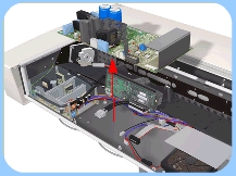
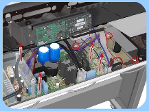
2.
Remove 3 screws from the Plastic Protector that covers the Driver
Board. |
|
|
|
|
 |
|
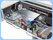
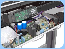
3. Remove
the Plastic Protector. |
|
|
|
|
 |
|
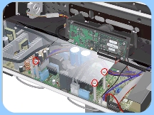
4. Remove
the 3 screws and 4 long nuts that secure the Driver Board. |
|
|
|
|
 |
|
5.
Disconnect ALL the cables from the Driver Board. |
|
|
If P2 is turned further Clockwise, LED
4 will eventually turn OFF. If both LED's are ON, the lamp driver
is within the acceptable working range. If either of the LED's is
OFF, the lamp driver should be adjusted. |
| |
|
|