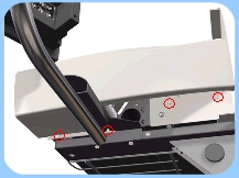
select printer | scanner series | disassembly instructions
hp designjet scanner series
» disassembly instructions
  » disassembly instructions
» introduction
» top cover
» guide plate
» left cover
» right cover
» rear cover
» top profile
» glass plate
» entry roller shield
» exit roller shield
» camera board
» camera motor
» camera lens
» power supply unit
» driver board
» fan
» main electronics board
» smart card reader
» interface board card
» interface board
» stepper motor
» fluorescent lamp
» rollers
» media detector wires
» media sensors
» belt
» bottom cover
» mirror chassis
» lamp sensor
» reflector assembly
» stitching wire
» white background assembly
» thickness sensor
» part number selector
» exploded views
» service manual
» general information
» send feedback or
comments
 
right cover
Switch the printer, scanner and the PC OFF, and disconnect them from the power source prior to performing any maintenance.
1. Remove the » Top Cover
2. Remove the » Guide Plate
3. Remove 4 screws that secure the Right Cover from underneath.
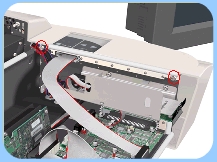
4. Remove 2 screws that secure the Right Cover from the side.
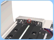
5. Remove 1 screw that secures the Right Cover from the top.
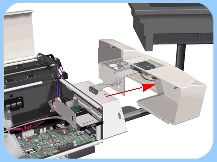
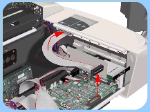
6. Disconnect the Operator Panel Cable from the Main Electronics and pass through the access hole.

7. Remove the Right Cover.

When installing the Right Cover, make sure you have the correct ID switch settings on the Operators Panel (0=OFF, 1=ON):

– hp designjet copier cc800ps: 00011000
– hp designjet 815mfp: 00011011
– hp designjet scanner 4200: 00100101

© 1994-2006 Hewlett-Packard Company