 |
|
|
 |
|
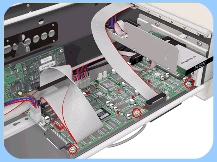
2. Remove
3 screws that secure the Main Electronics Board. |
|
|
|
|
 |
|
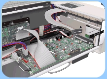
3. Disconnect ALL the cables from the Main Electronics Board. |
|
|
|
|
 |
|
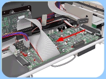
4. Move
the Main Electronics Board to the left to disconnect it from the connector
and to release it from the 3 plastic locators (located at the rear
of the Board). |
|
|
|
|
 |
|
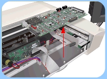
5. Remove
the Main Electronics Board from the scanner. |
|