select printer
|
scanner series
|
disassembly instructions
hp designjet scanner series
select printer
1000/1000 plus series
500/800 series
5000/5500 series
multi-roll feeder
10ps/20ps/30/30n/50ps
scanner series
70/100/100plus/110plus
90/120/130 series
4000 series printers
4500 series printers
9000s series printers
10000s series printers
Z2100/Z3100 series
8000s series printers
»
disassembly instructions
»
disassembly instructions
»
introduction
»
top cover
»
guide plate
»
left cover
»
right cover
»
rear cover
»
top profile
»
glass plate
»
entry roller shield
»
exit roller shield
»
camera board
»
camera motor
»
camera lens
»
power supply unit
»
driver board
»
fan
»
main electronics board
»
smart card reader
»
interface board card
»
interface board
»
stepper motor
»
fluorescent lamp
»
rollers
»
media detector wires
»
media sensors
»
belt
»
bottom cover
»
mirror chassis
»
lamp sensor
»
reflector assembly
»
stitching wire
»
white background assembly
»
thickness sensor
»
part number selector
»
exploded views
»
service manual
»
general information
»
send feedback or
comments
interface board cover
Switch the printer, scanner and the PC OFF, and disconnect them from the power source prior to performing any maintenance.
1.
Remove the
»
Top Cover
2.
Remove the
»
Right Cover
3.
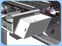
Remove 18 screws that secure the Interface Board Cover.
4.
Pull out the Interface Board Cover slightly and disconnect the cable that is connected to the Interface Board from inside.
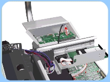
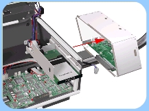
5.
Remove the Interface Board Cover from the scanner.
privacy statement
using this site means you accept its terms
© 1994-2006 Hewlett-Packard Company