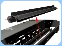
select printer | scanner series | disassembly instructions
hp designjet scanner series
» disassembly instructions
  » disassembly instructions
» introduction
» top cover
» guide plate
» left cover
» right cover
» rear cover
» top profile
» glass plate
» entry roller shield
» exit roller shield
» camera board
» camera motor
» camera lens
» power supply unit
» driver board
» fan
» main electronics board
» smart card reader
» interface board card
» interface board
» stepper motor
» fluorescent lamp
» rollers
» media detector wires
» media sensors
» belt
» bottom cover
» mirror chassis
» lamp sensor
» reflector assembly
» stitching wire
» white background assembly
» thickness sensor
» part number selector
» exploded views
» service manual
» general information
» send feedback or
comments
 
reflector assembly
Switch the printer, scanner and the PC OFF, and disconnect them from the power source prior to performing any maintenance.
1. Remove the » Top Cover

2. Remove the » Guide Plate

3. Remove the » Glass Plate
4. Remove the » Left Cover
5. Remove the » Right Cover
6. Remove the » Bottom Cover
7. Remove the » Mirror Chassis
8. Disconnect the Cable for the Lamp Sensor.
9. Remove 12 screws from the Reflector Assembly.
10. Remove the Reflector Assembly from the scanner.
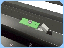
To prevent damage to the Stitching Wires when replacing the Reflector Assembly, the notches in the Reflector Assembly 
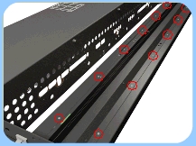
must be aligned with the Stitching Wires. This can be done by carefully keeping the holes for the fixing screws aligned with the holes in the Scanner Chassis.
© 1994-2006 Hewlett-Packard Company