| |
|
 |
|
|
| |
1. Remove
the Center Cover |
| |
|
| |
|
2. Remove the Right
End Cover |
| |
|
|
| |
|
3. Remove the Left
End Cover |
| |
|
|
| |
|
4. Remove
the Electronics module |
| |
|
|
| |
|
5. Remove the Power
Supply Unit |
| |
|
|
| |
|
6. Remove the Service
Station |
| |
|
|
| |
|
7. Remove the Starwheel
Assembly |
| |
|
|
| |
8. Remove the Print
Platen Assembly |
| |
|
| |
9. Remove the Spittoon
(if installed) |
| |
|
| |
10. Remove the Pivot
Assembly |
| |
|
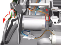 |
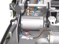
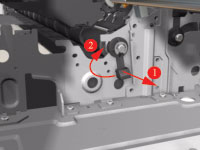
11. Disconnect the
Paper-Axis and Encoder cables. |
| |
|
 |
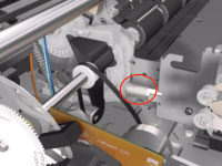
12. Remove 1 T-10
screw that secures the Paper-Axis Motor Mount. |
| |
|
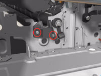 |
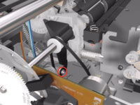
13. Remove 2 T-10
screws that secure the Pivot Assembly Support on the right hand side
of the Printer. |
| |
|
 |
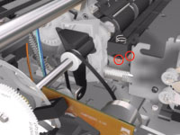
14. Remove the Pivot
Assembly Support from the Printer. |
| |
|
 |
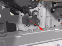
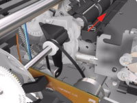
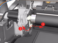
15. Release the
locking mechanism from the right hand side of the Printer. |
| |
|
 |
16. Remove 1 T-10
screw and nut that secures the Feed-Roller Support on the left hand
side of the Printer. |
| |
|
 |
17. Remove 2 T-10
screws that secure the bracket on the left hand side of the Printer.
|
| |
|
 |
18. Remove the Bracket
from the Printer. |
| |
|
 |
19. Release the
locking mechanism from the left hand side of the Printer. |
| |
|
 |
20. Release the
Spring from the Bracket. |
| |
|
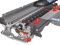 |
21. Raise the locks
so that they are aligned with the cutouts and lift out the Feed Roller
Assembly (including the Paper-Axis Motor) from the Printer. |
| |
|