| |
|
 |
|
|
| |
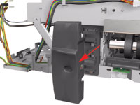
1. Remove
the Cleanout Assembly |
| |
|
| |
|
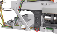
2. Remove the Center
Cover |
| |
|
|
| |
|
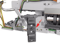
3. Remove the Right
End Cover |
| |
|
|
| |
|
4. Remove
the Left End Cover |
| |
|
|
| |
|
5. Remove the
Electronics Module |
| |
|
|
| |
|
6. Remove the Power
Supply Unit |
| |
|
|
| |
|
7. Remove the Service
Station |
| |
|
|
| |
8. Remove the Encoder
Strip |
| |
|
| |
9. Remove the Ink Supply tubes |
| |
|
| |
10. Remove the Carriage Assembly |
| |
|
 |
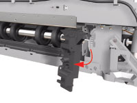
11. Remove 4 screws
that secure the Hanger Assembly on the left hand side of the Printer.
|
| |
|
 |
12. Remove 1 screw
that secures the Hanger Assembly on the left hand side of the Printer.
|
| |
|
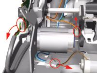 |
13. Disconnect the
Paper-Axis, Encoder and Ramp Motor cables. |
| |
|
 |
14. Remove 1 screw
from the Rear Left Trim Bracket. |
| |
|
 |
15. Remove the Rear
Left Trim Bracket from the Printer. |
| |
|
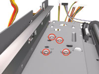 |
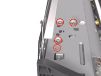
16. Remove 4 screws
that secure the Hanger Assembly on the right hand side of the Printer.
|
| |
|
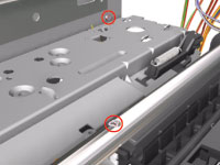 |
17. Remove 2 screws
that secure the Hanger Assembly on the right hand side of the Printer.
|
| |
|
 |
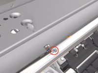
18. Remove 1 T-10
screw from the Rear Right Trim. |
| |
|
 |
19. Remove the Rear
Right Trim from the Printer. |
| |
|
 |
20. Remove 1 screw
from the Rear Right Trim Bracket. |
| |
|
 |
21. Remove the Rear
Right Trim Bracket from the Printer. |
| |
|
 |
22. Remove the Hanger
Assembly from the Printer. |
| |
|
|
If there are any cables still
attached between the Hanger
Assembly and the Printer then
disconnect them before removing
the Hanger Assembly. |
|
| |
|
|
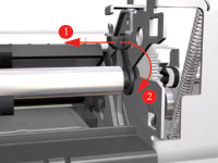 |
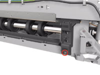
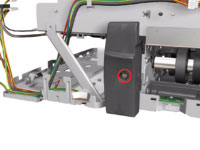
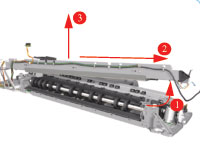
23. Release the
locking mechanism that secures the Pick Assembly on the right hand
side of the printer (looking from the rear). |
| |
|
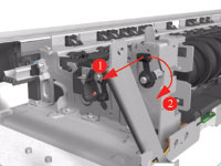 |
24. Release the
locking mechanism that secures the Pick Assembly on the left hand
side of the printer (looking from the rear). |
| |
|
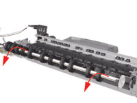 |
25. Raise the locks
so that they are aligned with the cutouts and lift out the Pick Assembly
from the Printer. |
| |
|