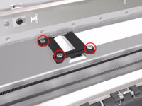
8. Remove 3 T-10 screws that secure the
Trailing Cable Clip to the Chassis.
9. Release the Trailing Cable Clip from the
Chassis.
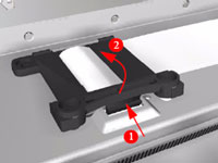
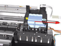
10. Release the
Trailing Cable from the Chassis.
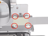
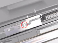
11. Remove 2 T-10 screws that secure the
Turnaround Stopper. Remove the
Turnaround Stopper from the Printer.
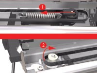
12. Release the Belt from the Carriage Motor by pushing in the Turnaround Assembly (right hand side of the printer) and at the same time releasing the Belt from the Motor on the left hand side of the printer).
13. Slide the Carriage
Assembly to the right and out of the Printer.
14. If the Carriage
Assembly is to be replaced, make sure that you remove the belt (in
order to install it on the new carriage). To remove the belt see carriage
belt.
If the Carriage is replaced by a new one, make
sure that you perform the PRS Adjustment procedure.
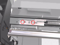
Installation of the Carriage Assembly - IMPORTANT
After re-installing the Carriage Assembly and Belt, take note of these steps for the correct installation of the Turnaround Stopper. These steps must be followed in exactly the same sequence:
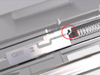
1. Place the Turnaround Stopper in to position and locate the slot in the Stopper on to the Turnaround Assembly. This step is very important since it will determine the space between the Stopper and the Turnaround Assembly.
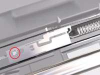
2. Insert the first screw (left) and tighten it.
3. Insert the 2nd screw (right) and tighten it.
As you tighten the screw you should notice
that the slot in the Stopper will rise away
from the Turnaround Assembly.
After the installation of the Carriage Assembly and the Turnaround Stopper,
you must first check that the Cutter cuts the media correctly (if the Printer has
the Rollfeed and Cutter installed).