select printer | 500/800 series | disassembly | disassembly instructions
hp designjet 500/800 series printers
» disassembly
  » disassembly instructions
» screw types
» Left Hand Cover
» Right Hand Cover
» Front Panel
» Window and Top Cover
» Media Deflectors
» Left End Roll-Feed
» Right End Roll-Feed
» Back Platen
» Media Sensor
» Formatter
» LAN Card
» Spittoon
» Electronics Module
» Power Supply
» Scan-Axis Motor
» Cutter Assembly
» Left Encoder Holder
» Cutter Bushing
» Cutter Guide Bracket
» Drive Roller Encoder Sensor
» Trailing Cable
» Ink Supply Station
» Interconnect PCA
» Service Station and Aerosol Fan
» Cutter Guide
» Print Platen
» Service Station Holder
» Interconnect Cable
» Ink Supply Tubes
» Vacuum Fan
» Pinch-Arm
» Pinch-Arm Mechanism
» Pinch-Arm Lever
» Pinch-Arm Sensor
» Fork Idler, Tensioner and Idler Pulley
» Encoder Strip
» Carriage Assembly
» Paper-Axis Motor
» Drive Roller
» Gear Assemblies
  » disassembly videos
» send feedback or
comments
 
» Trailing Cable

NOTE: Refer to the table on » Screw Types for information on screw types.


1. Perform the Service Utility "Unlock Carriage" » Unlock Carriage.

NOTE: Switch off the Printer after performing this Utility.


2. Remove the Left Hand Cover » Left Hand Cover.

3. Remove the Top Cover and Window » Window and Top Cover.

4. Manually move the carriage to the correct position to remove the Tubes Assembly from the Carriage.

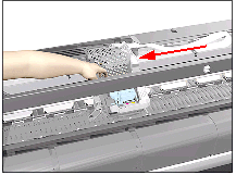
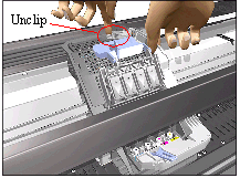
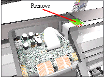
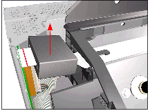
5. Release the latch and lift up the Carriage Cover.


6. Remove all the Printheads.

7. Loosen 1 T-8 screw that secures the Tubes to the Carriage.

8. Unclip the Tubes from the Carriage and lift up.

9. Move the Tubes Assembly clear from the Carriage Assembly.

10. Close the Carriage Cover.

11. Unclip the Carriage Cover (clip located on the left hand side of the Carriage - use a screwdriver if necessary).

12. Remove the clip securing the Trailing Cable.

13. Disconnect the Trailing Cable from the Carriage Assembly.

14. Slide the Trailing Cable out of the clip inside the Carriage Assembly and then lift up to free it from the Carriage.

15. Move the Carriage Assembly to the right so that the Trailing Cable clips on the beam are visible.

16. Release ALL the clips on the beam that secure the Trailing Cable.

17. Slide the Plastic Holder, that kept the Trailing Cable flat, to the right to release it from the retaining clip.

18. Remove the Plastic Holder from the Printer.

19. Release the Trailing Cable clips.

20. Disconnect the Trailing Cable from the Electronics Module.

21. Unclip the Ferrite and remove.

22. Slide the Trailing Cable through the Carriage Assembly and remove.

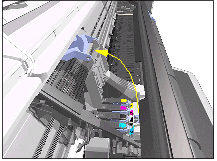
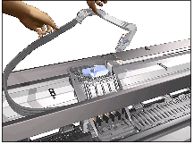
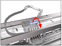
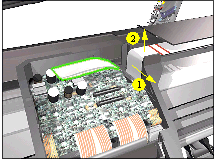
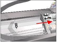
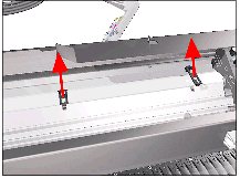
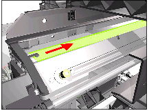
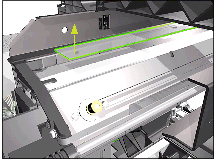
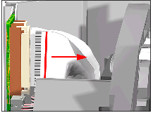
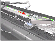
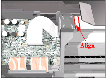
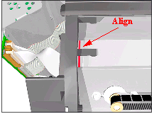
Installing the Trailing Cable

NOTE: When installing the Trailing Cable, make sure that you align the red lines on the Trailing Cable as shown in these drawings.

© 1994-2006 Hewlett-Packard Company