select printer
|
4000 series
|
disassembly
|
disassembly instructions
hp designjet 4000 series printers
1000/1000 plus series
500/800 series
5000/5500 series
multi-roll feeder
10ps/20ps/30/30n/50ps
scanner series
70/100/100plus/110plus
90/120/130 series
4000 series printers
4500 series printers
9000s series printers
10000s series printers
Z2100/Z3100 series
8000s series printers
»
disassembly instructions
»
Introduction
»
Screw Types
»
Window
»
Right Cover
»
Left Cover
»
Top Cover
»
Rear Door
»
Right Connector Cover
»
Left Connector Cover
»
Front Panel
»
Service Station
»
Vacuum Fan
»
Aerosol Fan
»
Drop Detector
»
Ink Supply Tubes and Trailing Cable
»
ISS to Cartridge Cables
»
Cutter Assembly
»
Ink Supply Station
»
APS Assembly
»
Most Left Spittoons
»
Middle Left Spittoons
»
Encoder Strip and Encoder Sensor
»
Carriage PCA
»
Carriage Flex Cables
»
Carriage Assembly
»
Belt Assembly
»
Scan-Axis Motor
»
Media-Axis Motor
»
Interconnect PCA
»
EIO to PCA Interface Card
»
Gamut PCI PCA
»
Memory Module
»
Main PCA Formatter
»
Hard Disk Drive
»
Power Supply Unit
»
PrintMech PCA
»
Formatter Battery
»
Line Sensor
»
Media Deflector
»
Front Platen
»
Center Platen
»
Cartridge Trays
»
Input Roller
»
Push-Push
»
Media Sensor
»
Encoder Disc and Sensor
»
Media Lever
»
Media Lever Sensor
»
Pinchwheel Assembly
»
Center Guide
»
Drive Roller
»
Right Rollfeed Module Assembly
»
Right Spindle Lever
»
send feedback or
comments
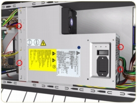
Power Supply Unit (PSU)
Removal
Switch off the product and remove the power cable.
1.
Remove the
Right Connector Cover
.
2.
Remove the JetDirect Card (if installed).
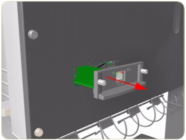
3.
Remove three T-15 screws (
Type A
) that secure the Main PCA cover.
4.
Remove the Main PCA Cover from the Printer.
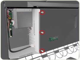
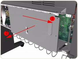
5.
Remove three T-15 screws (
Type A
) that secure the PSU cover.
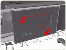
6.
Remove the PSU Cover from the Printer.
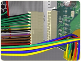
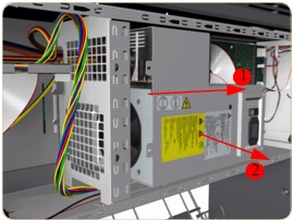
7.
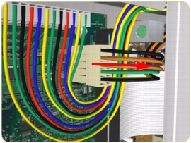
Disconnect the Power Supply and Interconnect cables from the PrintMech PCA.
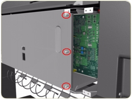
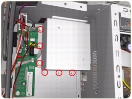
8.
Remove six T-10 screws (
Type I
) that secure the Interconnect PCA Cover.
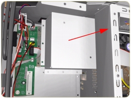
9.
Remove the Interconnect PCA Cover from the Printer.
10.
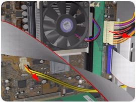
Disconnect one cable from the Interconnect PCA.
11.
Disconnect two cables from the Main PCA.
12.
Disconnect one cable from the Gamut PCA.
13.
Disconnect one cable from Hard Disk Drive.
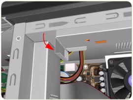
14.
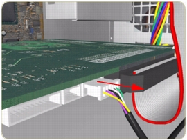
Bend the edge of the Cable Support Bracket so that it can be released.
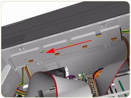
15.
Move the Cable Support Bracket to the left to release it from the Electronics Module.
16.
Lower the Cable Support Bracket so that the cables can be accessed.
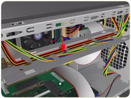
17.
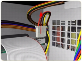
Release the Power Supply Cable from the Cable Support Bracket.
18.
Remove four T-10 screws (
Type I
) that secure the Power Supply Unit.
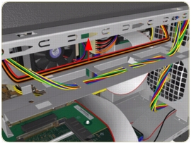
19.
Route the cables through the hole in the Electronics Module and remove the Power Supply Unit from the Printer.
privacy statement
using this site means you accept its terms
© 1994-2006 Hewlett-Packard Company