select printer
|
4000 series
|
disassembly
|
disassembly instructions
hp designjet 4000 series printers
1000/1000 plus series
500/800 series
5000/5500 series
multi-roll feeder
10ps/20ps/30/30n/50ps
scanner series
70/100/100plus/110plus
90/120/130 series
4000 series printers
4500 series printers
9000s series printers
10000s series printers
Z2100/Z3100 series
8000s series printers
»
disassembly instructions
»
Introduction
»
Screw Types
»
Window
»
Right Cover
»
Left Cover
»
Top Cover
»
Rear Door
»
Right Connector Cover
»
Left Connector Cover
»
Front Panel
»
Service Station
»
Vacuum Fan
»
Aerosol Fan
»
Drop Detector
»
Ink Supply Tubes and Trailing Cable
»
ISS to Cartridge Cables
»
Cutter Assembly
»
Ink Supply Station
»
APS Assembly
»
Most Left Spittoons
»
Middle Left Spittoons
»
Encoder Strip and Encoder Sensor
»
Carriage PCA
»
Carriage Flex Cables
»
Carriage Assembly
»
Belt Assembly
»
Scan-Axis Motor
»
Media-Axis Motor
»
Interconnect PCA
»
EIO to PCA Interface Card
»
Gamut PCI PCA
»
Memory Module
»
Main PCA Formatter
»
Hard Disk Drive
»
Power Supply Unit
»
PrintMech PCA
»
Formatter Battery
»
Line Sensor
»
Media Deflector
»
Front Platen
»
Center Platen
»
Cartridge Trays
»
Input Roller
»
Push-Push
»
Media Sensor
»
Encoder Disc and Sensor
»
Media Lever
»
Media Lever Sensor
»
Pinchwheel Assembly
»
Center Guide
»
Drive Roller
»
Right Rollfeed Module Assembly
»
Right Spindle Lever
»
send feedback or
comments
Service Station
Removal
Switch off the product and remove the power cable.
1.
Remove the
Right Cover
.
2.
Remove the
Rear Door
.
3.
Remove the
Right Connector Cover
.
4.
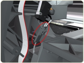
Disconnect the cable from the Printhead Cleaner Door Switch.
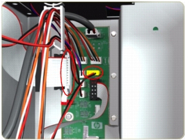
5.
Disconnect the Service Station and Aerosol Fan Cables from the Interconnect PCA.
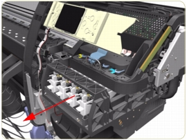
6.
Uncap the Carriage Assembly by manually pulling out the Printhead Cleaner tray.
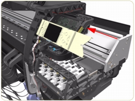
7.
Move the Carriage Assembly out of the Service Station.
8.
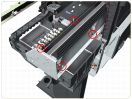
Remove four T-15 screws (
Type J
) that secure the Service Station to the Chassis.
When removing the screws, please be very careful NOT to damage the Encoder Strip.
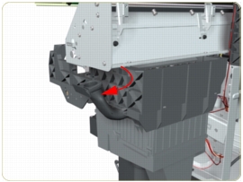
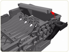
9.
Disconnect the Aerosol Fan Tube from the Chassis.
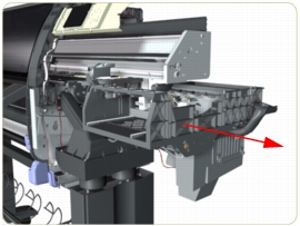
10.
Remove the Service Station from the Printer.
After installing the NEW Service Station, make sure you perform the following Service Utility:
Reset Counter PHC spittoon
.
After installing the NEW Service Station, make sure you perform the following Service Calibration:
Service Station Calibration
.
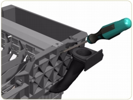
Removal of the Service Station Scraper
1.
Release the clip securing the Scraper to the Service Station.
2.
Remove the Scraper from the Service Station.
privacy statement
using this site means you accept its terms
© 1994-2006 Hewlett-Packard Company