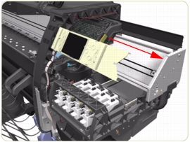
4. Move the Carriage Assembly to the extreme right of the Printer.
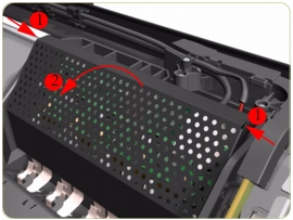
5. Press the two side of the Carriage PCA Cover and unclip from the Carriage Assembly.
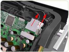
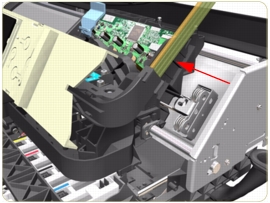
6. Disconnect the Trailing Cable from the Carriage PCA.
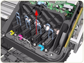
7. Open the Carriage Cover and remove ALL the Printheads from the Carriage Assembly.
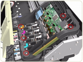
8. Remove five T-15 screws (Type G) that secure the Ink Supply Tubes to the Carriage Assembly.
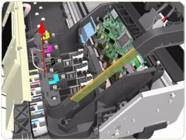
9. Remove the Ink Supply Tubes from the Carriage Assembly and safely place to one side of the Printer.
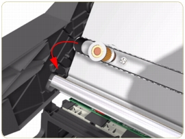
10. Disconnect the Aerosol Fan Tube from the Chassis.
11. Remove one T-15 screw (Type A) that secures the Belt Tensioner to the Chassis.
12. Move the Carriage Assembly slightly away from the right Scan-Axis Bracket.
13. Release the Carriage Belt from the Scan-Axis Motor on the left hand side of the Printer.
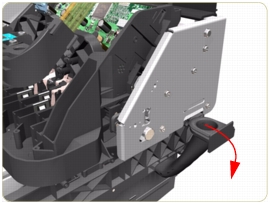
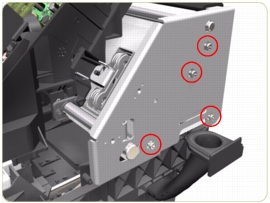
14. Remove four T-20 screws (Type N) that secure the right Scan-Axis Bracket.
Note that these are Chassis screws and in normal circumstances should NEVER be removed, but in this case we need to remove them in order to remove the Carriage Assembly.
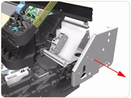
15. Remove the right Scan-Axis Bracket from the Printer.
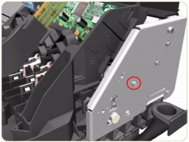
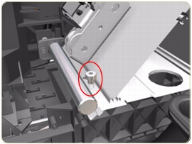
16. Remove the Carriage Stopper Screw (T-25) from the Chassis.
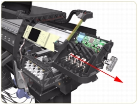
17. Slide the Carriage Assembly (including the belt) to the right and out of the Printer.
18. If the Carriage Assembly is to be replaced, make sure that you remove the Belt, the Carriage PCA, Encoder and Line Sensors and the Cutter Assembly (in order to install them on the new Carriage Assembly).
After installing the NEW Carriage Assembly, make sure you perform the following Service Utility:
Reset life counter Carriage ME.
After installing the NEW Carriage Assembly, make sure you perform the following Service Calibrations: