| |
|
||||||||||||||||||||||||||||||||||||||||||||
|
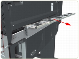
Pinchwheel AssemblyRemoval
Switch off the product and remove the power cable.
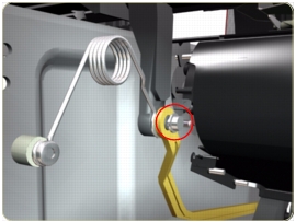
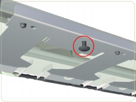
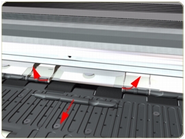
Removing individual Pinchwheels
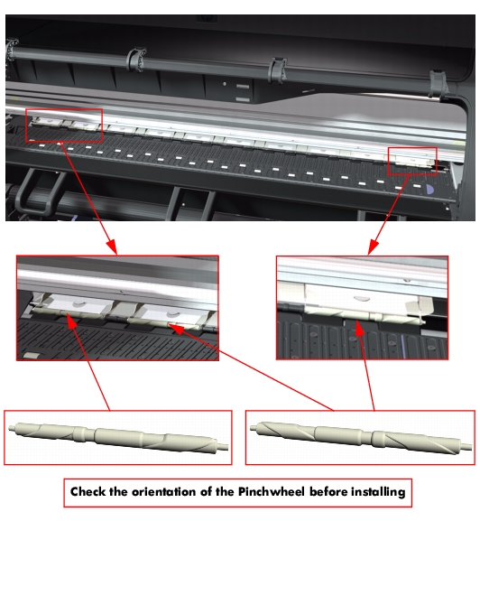
Important Information on Installation of Pinchwheels
The Pinchwheel Assembly contains 3 white Pinchwheels and several black Pinchwheels. The black Pinchwheels are symmetrical so can be installed without any problems, BUT the white Pinchwheels are NOT symmetrical so it is VERY IMPORTANT to install them correctly using the following illustration:
 |
||||||||||||||||||||||||||||||||||||||||||||
|
|||||||||||||||||||||||||||||||||||||||||||||