| |
|
||||||||||||||||||||||||||||||||||||||||||||||||||||||||||||||||||||||||||
|
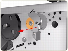
Drive RollerRemoval
Switch off the product and remove the power cable.
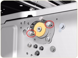
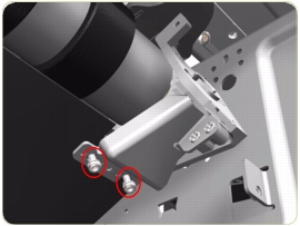
Installation of the Drive Roller When installing the Drive Roller, several different datums have to be met in order to ensure that the Drive Roller has no axial play. Use the following illustrations to ensure that ALL the datums are met:
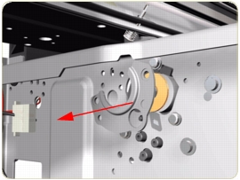
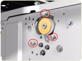
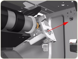
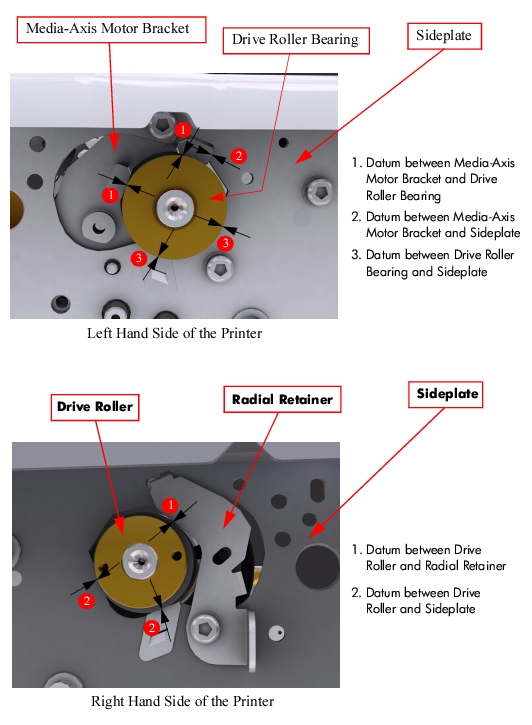 To make sure that ALL the datums are met when installing the Media-Axis Motor Bracket, make sure you follow these instructions:
|
||||||||||||||||||||||||||||||||||||||||||||||||||||||||||||||||||||||||||
|
|||||||||||||||||||||||||||||||||||||||||||||||||||||||||||||||||||||||||||
.jpg)
.jpg)
.jpg)