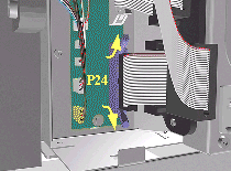
2. Remove
the Ferrite (if present) and disconnect the Front Panel cable from
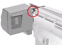
the Main PCA (P24) from the left side of the Electronics Module.
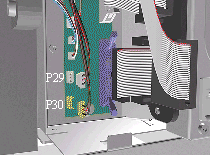
3. On
the Main PCA, disconnect the Aerosol Fan cable from position P30 and
the service station door from position P29.
NOTE: Take care
not to drop the Cover when removing the screws. Support the Cover
throughout the next step.
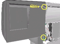
4. Remove
1 T-15 screw (Type F) and 1 T-25 screw (Type U) (bottom) from the
rear of the Right Hand Cover.
5.Open
the Top Cover.
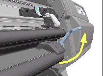
6. Raise
the Media Lever.
NOTE: Take care not
to drop the Cover when removing the screws. Support the Cover throughout
the next step.
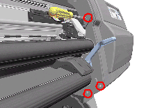
7. Remove
3 T-15 (Type F) screws from the front of the Right Hand Cover.
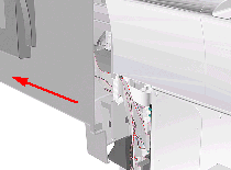
8. To
release the cables, carefully pull out the Right
Hand Cover until the cables can be accessed.
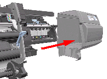
9. Remove
the Right Hand Cover.
TIP: To check
correct functioning of serviced parts on the Printer axis you can
do the following:
1. Reinsert
the top T-15 screw (Type F) at the rear of the Printer. 2.
Hang the Cover on the screw. 3. Connect all cables
at the Rear of the Right Cover and turn on the Printer.
Installation of Right
Hand Cover
NOTE: Make sure the Front Panel cable and the Aerosol Fan cables
are secured inside the Right Hand Cover with cable clamps and retaining
pins.
WARNING: Make sure
cables pass through slot at rear of chassis on the right hand side
otherwise the Cover cannot be properly installed and cables may
be damaged.