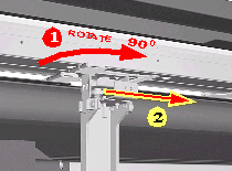
select printer | 5000/5500 series | disassembly | disassembly instructions
hp designjet 5000/5500 series printers
» disassembly instructions
  » disassembly instructions
» Top Cover
» Left Hand Cover
» Right Hand Cover
» Front Panel
» Left Rear Cover
» Right Rear Cover
» Extension Cover
» Media Lever
» Right Hand Trim
» Left Hand Trim
» Back Cover
» Ink Tubes System
» EMC Covers
» Encoder Strip
» Trailing Cable
» Tensioner Assembly
» Carriage and Belt
» Line Sensor
» Scan-Axis Motor
» Cutter Assembly
» Ink Supply Station
» Air Pressurization System
» Service Station
» Drop Detector
» Hard Disk Drive
» LAN Card
» Memory and BootROM DIMM's
» EM cover
» Main PCA
» Power Supply Unit
» Ink Supply Station PCA
» Ink Leak Detector
» Cooling Fans
» Electronics Module
» Pinch-Wheels
» Pinch-Wheel Cam
» Vacuum Fan
» Paper-Axis Motor
» Booster Fan
» Media Sensor
» Entry Roller
» Center Guide
» Drive Roller Gear
» Front Platen
» Center Platen
» Deflectors
» PCI-to-IDE PCA
» Heater
» Tube Guide Door
» disassembly videos
» send feedback or
comments
 

Pinch-Wheels


WARNING: Switch off the Printer and remove the Power Cord.

 
  1. Remove the Top Cover
       
      2. Remove the Back Cover


3. Remove the Electronics Module

       
      4. Remove the EMC Covers


For the next steps place the Media Lever in the UP position.

 
5. Remove the following T-20 screws (Type Q):
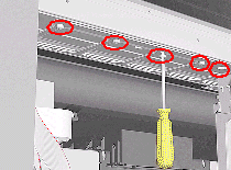
 
-For the 60" Model remove 4 screws from each group of 4 Pinch-Wheels (5 groups in total).
-For the 42" Model remove 4 screws from each group of 4 Pinch-Wheels (3 groups in total) and 2 screws from the one group with 2 Pinch-Wheels.
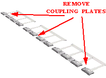
       
    6. First remove lateral Pinch-Wheels with their Coupling Plates.


NOTE: For Pinch-Wheel groups installed around the Mount Brackets do the following:

 
7. From the front of the Printer, remove the Coupling Plate corresponding to the position of the Mount Bracket.
 

-3 Mount Brackets in the 60" Model.
-1 Mount Bracket in the 42" Model.

       
    8. From the rear of the Printer, rotate the group (90 degrees) and pull it through the gap left by the Coupling Plate.


Installation of Pinch-Wheels

NOTE: During installation, make sure you install the White Pinch-Wheels at each end of the Printer axis.

© 1994-2006 Hewlett-Packard Company