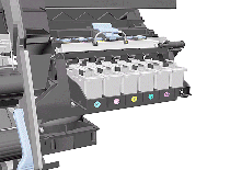
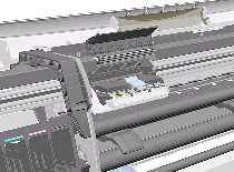
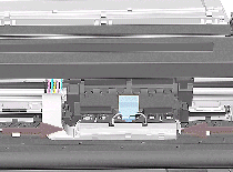
Carriage Assembly and Belt
WARNING: Switch off the Printer and remove the Power Cord.
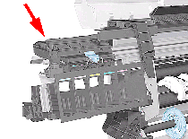
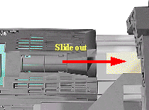
3. Remove the Right Hand Cover
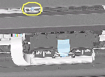
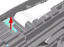
NOTE: Remove Trailing Cable Ferrites if they fall into the Carriage
-3 for 60" Model. -1 for 42" Model.
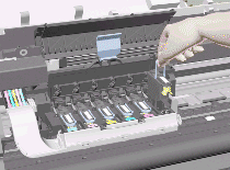
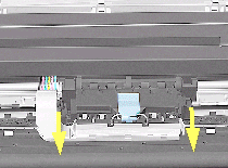
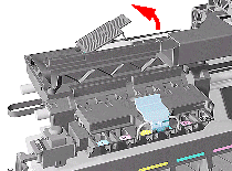
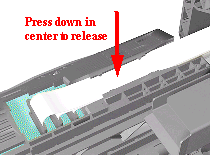
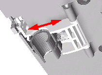
17. Remove the Trailing Cables from the Trailing Cable Holder.
TIP: Press the Trailing Cables firmly in the center to release.
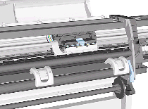
Installation of Carriage and Belt
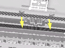
NOTE: Before installation, clean and oil the Slider Rods using the User's Slider Rods Lubrification Kit.
WARNING: When installing the Carriage Assembly and Belt, make sure you install it as follows:
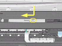
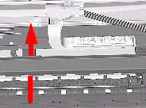
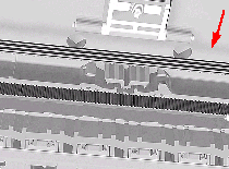
1. Insert belt as indicated on the underside of Carriage.
TIP: An arrow on the bottom of the Carriage indicates position and direction.
NOTE: Perform the following Service Calibrations after the installation of the Carriage Assembly:
-Scan Axis (See Scan-Axis Calibration). -Service Station (See Service Station Calibration). -Carriage Height (See Carriage Height Calibration). -Printhead Alignment. -Color Calibration.