|
| |
|
 |
|
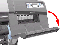
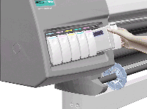
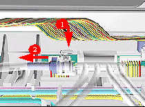
1.
Open the Right Cover door. |
| |
|
|
|
| |
 |
|
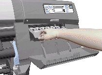
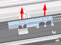
2. Pull
out the Printhead Cleaner Carriage. |
| |
|
|
|
| |
 |
|
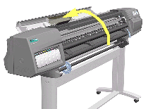
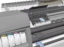
3. Open
the Top Cover. |
| |
|
|
|
| |
 |
|
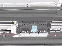
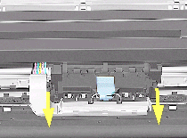
4. Pull
the Carriage out along the Printer to the position shown. |
| |
|
|
|
| |
 |
|
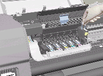
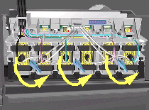
5. Lift
up the Carriage Cover and remove ALL the Printheads and close the
Carriage Cover. |
| |
|
|
|
| |
 |
|
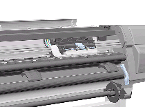
6. Slide
the Carriage to the position shown. |
| |
|
|
|
| |
 |
|
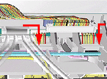
7. Push
in the 2 retaining clips either side of the Printhead Tube Connector. |
| |
|
|
|
| |
 |
|
8. Pull
the Printhead Tube Connector towards you. |
| |
|
|
|
| |
 |
|
9. Push
the button to release the Printhead Tubes in the Carriage. |
| |
|
|
|
| |
 |
|
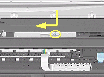
10. Release
the Retaining Clip by pulling it away from the holding brackets. |
| |
|
|
|
| |
 |
|
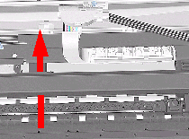
11. Pull
the Printhead Tube Connector up between the two Tube Guides. |
| |
|
|
|
| |
 |
|
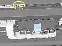
12. Lift
out the blue Retaining Clip. |
| |
|
|
|
| |
 |
|
13. Remove
ALL the Ink Cartridges from the Printer. |
| |
|
|
|
| |
 |
|
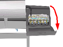
14. Open
the door at the back of the Left Cover. |
| |
|
|
|
| |
 |
|
15. Disconnect
the Electrical Cable from the rear of the Ink Cartridge Tube Connector. |
| |
|
|
|
| |
 |
|
16. Disconnect
the Air Tube. |
| |
|
|
|
| |
 |
|
17. Twist
the 3 latches at the rear of the Ink Cartridge Tube Connector and
release the complete Assembly. |
| |
|
|
|
| |
 |
|
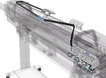
18. The
complete assembly can now be removed by sliding the Ink Cartridge
Connector out from the rear of the Left Hand Cover. |
| |
|
|
|
|
| |
|
|
|
1.
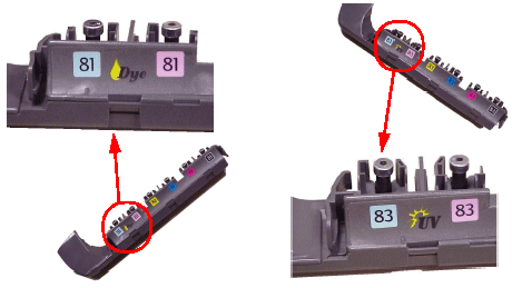
Install the Setup Printheads (refer to the User's Guide). |
| |
|
|
|
| |
|
|
2. Connect
the Power Cable and turn on the main Power Switch at the rear of the
Printer. |
| |
|
|
|
| |
 |
|
3. The
Front Panel warns that there are no Ink Cartridges installed. |
| |
|
|
|
| |
 |
|
4. Install
the Ink Cartridges (refer to the User's Guide for details). |
| |
|
|
| |
|
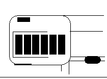
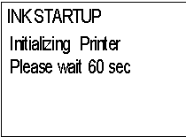
5. The
Front Panel displays the message shown. |
| |
|
|
| |
|
6. Wait
about 60 seconds for the next instruction. |
| |
|
|
| |
|
7. Remove
the Setup Printheads from the Printhead Carriage. |
| |
|
|
| |
|
8. Install
the Printheads and the Printhead Cleaners (refer to the User's Guide
for details). |
| |
|
|
|