 |
| |
 |
|
 |
1.
Remove the Top Cover Assembly |
| |
|
|
|
| |
|
|
2. Remove
the Right Rear Cover |
| |
|
|
|
| |
|
|
3. Remove
the Right Hand Cover |
| |
|
|
|
| |
|
|
4. Remove
the Left Hand Cover |
| |
|
|
|
| |
 |
|
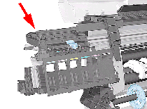
5. Slide
the Carriage to the left side of the Printer. |
| |
|
|
|
| |
 |
|
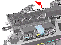
6. Unclip
and remove the Carriage Cover to access the Trailing Cable in the
Carriage. |
| |
|
|
|
| |
 |
|
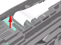
7. Carefully
disconnect the Trailing Cables (3) from the connectors in the Carriage
PCA. |
| |
|
|
|
 |
| |
 |
 |
 |
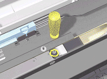
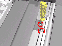
11. Remove
the T-20 screw (Type C) from the Trailing Cable Clip on the left.
|
| |
|
|
|
 |
| |
 |
 |
 |
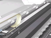
12.
Remove 2 T-10 screws (Type I) from the Trailing Cable Clip on the
right. |
| |
|
|
|
 |
| |
 |
 |
 |
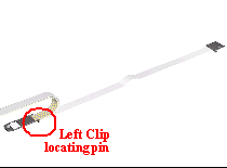
13.
Carefully lift the Clips and the Trailing Cable from the Printer. |
| |
|
|
|
 |
| |
 |
 |
 |
1.
Install the Trailing Cable starting from the Clip on the
left as this will provide a reference point for adjusting the length
of the Trailing Cable. |
| |
|
|
|
| |
 |
|
2. Insert
the Trailing Cable Guide into the Carriage and connect the Trailing
Cables. |
| |
|
|
|
 |
| |
 |
|
 |
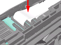
3.
Insert the Trailing Cable through the Chassis slot next to the Trailing
Cable Clip on the right (see diagram in step 4).
|
| |
|
|
|
| |
 |
|
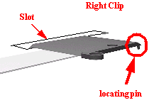
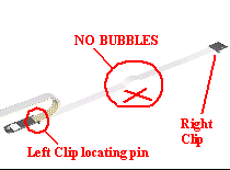
4. Place
the Right Trailing Cable Clip in position and adjust the length of
the Trailing Cable. |
| |
|
|
|
 |
| |
 |
 |
 |
TIP:
Make sure the Trailing Cable is flat on the chassis without bubbles. |
| |
|
|
|
 |
| |
 |
 |
 |
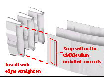
5.
Connect the Trailing Cables to the Main PCA. |
| |
|
|
|
