select printer | 5000/5500 series | disassembly | disassembly instructions
hp designjet 5000/5500 series printers
» disassembly instructions
  » disassembly instructions
» Top Cover
» Left Hand Cover
» Right Hand Cover
» Front Panel
» Left Rear Cover
» Right Rear Cover
» Extension Cover
» Media Lever
» Right Hand Trim
» Left Hand Trim
» Back Cover
» Ink Tubes System
» EMC Covers
» Encoder Strip
» Trailing Cable
» Tensioner Assembly
» Carriage and Belt
» Line Sensor
» Scan-Axis Motor
» Cutter Assembly
» Ink Supply Station
» Air Pressurization System
» Service Station
» Drop Detector
» Hard Disk Drive
» LAN Card
» Memory and BootROM DIMM's
» EM cover
» Main PCA
» Power Supply Unit
» Ink Supply Station PCA
» Ink Leak Detector
» Cooling Fans
» Electronics Module
» Pinch-Wheels
» Pinch-Wheel Cam
» Vacuum Fan
» Paper-Axis Motor
» Booster Fan
» Media Sensor
» Entry Roller
» Center Guide
» Drive Roller Gear
» Front Platen
» Center Platen
» Deflectors
» PCI-to-IDE PCA
» Heater
» Tube Guide Door
» disassembly videos
» send feedback or
comments
 

Main PCA


WARNING: This assembly does NOT include the PCI-to-IDE PCA (the small PCA that connects the Main PCA to the Hard Disk Drive) as it used to in the past. When installing the new Main PCA, make sure that you reuse the PCI-to-IDE PCA that was disassembled previously.


WARNING: If you are working with an hp designjet 5000 (C6090A/V/I, C6091A/V, C6095A/V/I, C6096A/V) and the new Main PCA has the following connectors, you do NOT need to use them (they can be ignored):


Removal

WARNING: Switch off the Printer and remove the Power Cord.

 
  1. Remove the LAN Card
       
      2. Remove the Left Rear Cover


3. Remove the Right Rear Cover

       
      4. Remove the Electronics Module Cover
       
      5. Remove the Hard Disk Drive (HDD)
       
      6. Remove all Memory and BootROM DIMM's


NOTE: Make sure you reinstall the Firmware/Memory DIMMs on the new Main PCA.

 
  7. Disconnect ALL Cables from the Electronics Module (see Installation of Main PCA for connections).
       
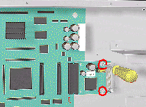
    8. Remove 2 T-10 screws (Type K) to remove the HDD controller.


NOTE: Make sure you reuse the PCI-to-IDE PCA when reassembling.

 
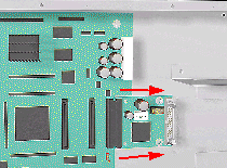
9. Disconnect the HDD Controller and remove from the Printer.
       
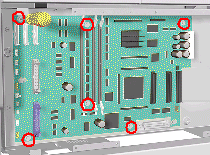
    10. Remove 6 T-10 screws (Type K) from the Main PCA.
       
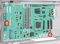
    11. Loosen 2 T-10 screws on the Main PCA.
       
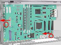
    12. Remove by sliding the Main PCA to the left and lifting out (see detail below).


NOTE: Detail of Main PCA removal.


Installation of Main PCA

NOTE: When the Main PCA has been replaced, perform the Backup EEROM (See EEROM Setup).


NOTE: If you replace the Main PCA and the HDD at the same time you must perform ALL Service Calibrations and the EEROM Setup Service Utility).


NOTE: If you are not sure how the cables are connected on the Main PCA, each connector is labelled with the name of the assembly to which it is connected.


NOTE: When installing the Hard Disk Drive, please refer to the instructions for the installation of the PCI-to-IDE PCA and the installation of the HDD Cable (See Hard Disk Drive).

© 1994-2006 Hewlett-Packard Company